This post is also available in:
Securing a connection in an application can be more complicated than it appears. To the average person, a clamp is simple – turn the screw and the clamp tightens up. But when you break down the interactions and try to quantify individual contributions, things aren’t as simple as they appear.
In this article, I will break down the transfer of energy in a worm-drive hose clamp to explore the theoretical framework – and disclose an interesting relationship between measured load, band tension, and radial load.
By identifying the common sources of undesirable energy transfer, you can minimize their effect on clamp load.
Load generation begins with the fastener. Energy is introduced into the system by torque applied to the screw, which is converted into strain energy and heat. Heat is an undesirable byproduct of relative movement between mating components.
Two readily apparent interactions occur in the fastener as a) the screw threads interact with the band and b) the bearing surface of the screw head is thrust against the housing. Additional, there is a significant amount of friction between c) the band and the clamped object (Figure 1).

Some clamped objects, such as rigid steel pipes, exhibit relatively low friction coefficients, while others, such as rubber hoses, have friction values which convert significantly higher amounts of energy into heat.
Strain energy is the potential energy stored in a body when deformed – think springs. As the rotating screw cinches down the clamp’s diameter, the band stretches slightly with the applied load. This tension in the band is the preferred energy transfer because it results in clamp load. Additionally, there is some strain energy developed in the hardware to oppose the bending moment generated by non-axial loading of the screw (Figure 2).

Now, ignoring all undesirable effects, let’s focus on just the clamp load that is generated. There are a variety of ways for measuring and reporting clamp load, and most engineers have seen this reported as either band tension, radial load, or in spider charts of measured load.
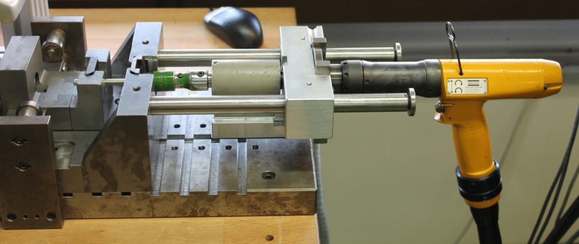
It’s not obvious how the different reported values correlate. A typical measuring device is simply a round mandrel that is divided into segments – anywhere from 2 to 8 segments is common (Figure 3 shows a two segment fixture, Figure 4 shows eight segments).
Now, to make sense of the measurement, one must distinguish between the following force values:
Deriving band tension for the two segment fixture is somewhat intuitive. When considering the free body diagram and assuming equal distribution of clamp load (Figure 5), the measured force is twice the band load.
However, it’s not clear how the measured load relates to radial load. Also, it is not possible to conduct the same analysis for band tension with the eight segment fixture. A general correlation between measured load, band tension, and radial load is shown in Figure 7.
. Figure 6: Spider chart of measured loads from ABA test method.")
Interestingly, these equations show that the radial load generated by a clamp is equal to the integral of the band tension around the circumference. So converting between radial load and band tension is as simple as scaling the values by a factor of 2π.
This relationship emphasizes the importance of generating uniform band tension to ensure proper sealing function. Furthermore, by identifying the common sources of undesirable energy transfer, one can target designs attributes to minimize their effect on generating clamp load.